Calulator Display Segments, Side Effects, and Side Channel Attacks
How I accidentally understood side channel attacks while revisiting the basics of computer hardware

- Miro
- 3 min read

This week, it happened. Just like clockwork the gears of my mind began to turn. Side channels, a concept once all too unfamiliar finally revelead its secrets to me, unravelling in all its beauty, while revisiting the basics of computer hardware.
While I have heard about side channel attacks before, likely in passing, I did not know the specifics. Prior to my understanding the concept, I did not look it up either, until now. I wish I’d done so sooner because it’s actually quite interesting.
Side channels or side bands, whatever you want to call them, are difficult to mitigate, given the binary nature of the circuitry we use. In order to mitigate them, however, one must first understand them.
Digital Logic Reloaded
A thought occurred to me while I was going through the lesson on digital logic on the ropper’s computing fundamentals course.
Consider the following:
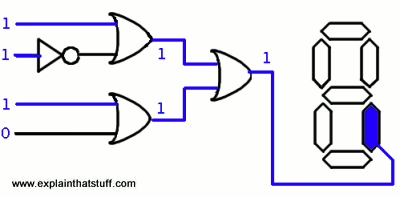
On a calculator, the numbers from 0-9 except the number 2 all need segment one of an lcd to light up (in addition to others). However the segment makes use of a logic circuit that looks like this:

With a boolean equation:
X = (A + B') + (C + D)
This circuit is not only capable of representing the number 0 - 9, but also the numbers 10 - 15, so the range of values represented are 0 - 15.
However, since there are only 10 symbols (0 - 9) in base-10, and this is a calculator display, we only need to represent the values 0 - 9 in this circuit. This makes the values 10 - 15, the side channel.
Meaning, we can get the circuit to do stuff that we did not intend. Which, in this case, does not really do much except light up a display. However if you can get the bits to overflow, bad things can happen - these are side effects (unintended consequences).
In the case of the number 7, the binary code 0111 is split into 4 inputs, rightly triggering the gates as follows:

This can be observed, in detail, by drawing up a truth table for the circuit.
| Value | A | B | C | D | X |
|---|---|---|---|---|---|
| 0 | 0 | 0 | 0 | 0 | 0 |
| 1 | 1 | 0 | 0 | 0 | 1 |
| 2 | 0 | 1 | 0 | 0 | 0 |
| 3 | 1 | 1 | 0 | 0 | 1 |
| 4 | 0 | 0 | 1 | 0 | 1 |
| 5 | 1 | 0 | 1 | 0 | 1 |
| 6 | 0 | 1 | 1 | 0 | 1 |
| 7 | 1 | 1 | 1 | 0 | 1 |
| 8 | 0 | 0 | 0 | 1 | 1 |
| 9 | 1 | 0 | 0 | 1 | 1 |
| 10 | 0 | 1 | 0 | 1 | 1 |
| 11 | 1 | 1 | 0 | 1 | 1 |
| 12 | 0 | 0 | 1 | 1 | 1 |
| 13 | 1 | 0 | 1 | 1 | 1 |
| 14 | 0 | 1 | 1 | 1 | 1 |
| 15 | 1 | 1 | 1 | 1 | 1 |